
Pontoon layout comparison
16 ft vs. 22 ft vs. 24 ft pontoons: floor plans & beam
Updated
The wrong floor plan can leave your pontoon’s boarding route crowded. Compare 16 ft, 22 ft and 24 ft pontoon floor plans by deck zone, then check how the chosen beam changes usable space. Start with Cove 16 for a compact footprint, or inspect Cove 22 and Cove 24 for their different lounge arrangements.
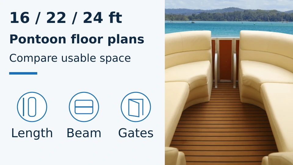
Start with the reference dimensions
Choose the smallest layout that accommodates your seating, stowed gear and boarding route, then verify it against a dimensioned drawing. In the Cove pontoon range, 16, 22 and 24 are model labels: the published reference lengths are 5 m, 6.8 m and 7.2 m. Beam is the boat’s width; it does not state the clear width between seats. The 2.3 m and 2.6 m choices on Cove 22 and Cove 24 are alternative configurations, so request the plan for the beam actually offered.
| Input or item | Reference value or source | Why it matters |
|---|---|---|
| Cove 16 | Model length 5 m; beam 2.3 m | Compact starting point; locate your essential gear before adding equipment |
| Cove 22 | Model length 6.8 m; beam 2.3 / 2.6 m | Choose one beam and request its matching layout |
| Cove 24 | Model length 7.2 m; beam 2.3 / 2.6 m | Inspect the different aft seating and chair arrangement |
| Clear aisle and gates | Measurements from the configured drawing | Cannot be calculated from model length or beam alone |
| Transport envelope | Maximum loaded boat-and-trailer dimensions | Trailer or fittings can extend beyond the stated boat width |
Reference dimensions checked October 20, 2026 against the published Cove model pages. Confirm deck length, overall dimensions and final arrangement in the written configuration; do not convert a model name into a measured length.
Compare the floor plans by deck zone
Read each plan from bow to stern and trace a route from the boarding gate to a seat and the helm. Cove 16’s reference drawing has forward curved lounges and an aft L-shaped seating area. Cove 22 shows longer forward seating runs and a different aft seat arrangement. Cove 24 shows paired aft lounge curves and two individual chairs around the middle-to-aft area. These are distinct furniture arrangements to inspect, rather than a promise that every larger model has a wider aisle.
The reference plans below face bow-up: port is on the left and starboard on the right. All show the helm on the right and a side opening on the left. They do not identify a final beam revision or provide dimensioned gate, chair or walkway clearances. Ask for those details on the layout attached to your offer.
| Model | Bow / social zone | Helm / passage zone | Aft zone | Dominant Failure Mode & Prevention |
|---|---|---|---|---|
| Cove 16 | Curved forward lounges; decide where bags and a cooler will be stowed | One helm chair beside the central route; inspect chair travel | L-shaped lounge with a table in the reference plan | Loose gear or the table narrows the route: mark stowage and the table position before approving the plan |
| Cove 22 | Forward lounges with longer straight seat sections in the drawing | Side opening meets the route beside the helm area | Port lounge and separate starboard seating in the reference plan | An assumed gate location misses your dock: match the proposed gate and approach to the actual berth |
| Cove 24 | Forward lounges with a table shown between them | Two individual chairs appear farther aft; check their occupied positions | Paired curved lounges with another table in the reference plan | A longer plan is assumed to solve chair/table interference: request narrowest-route measurements with those items in use |
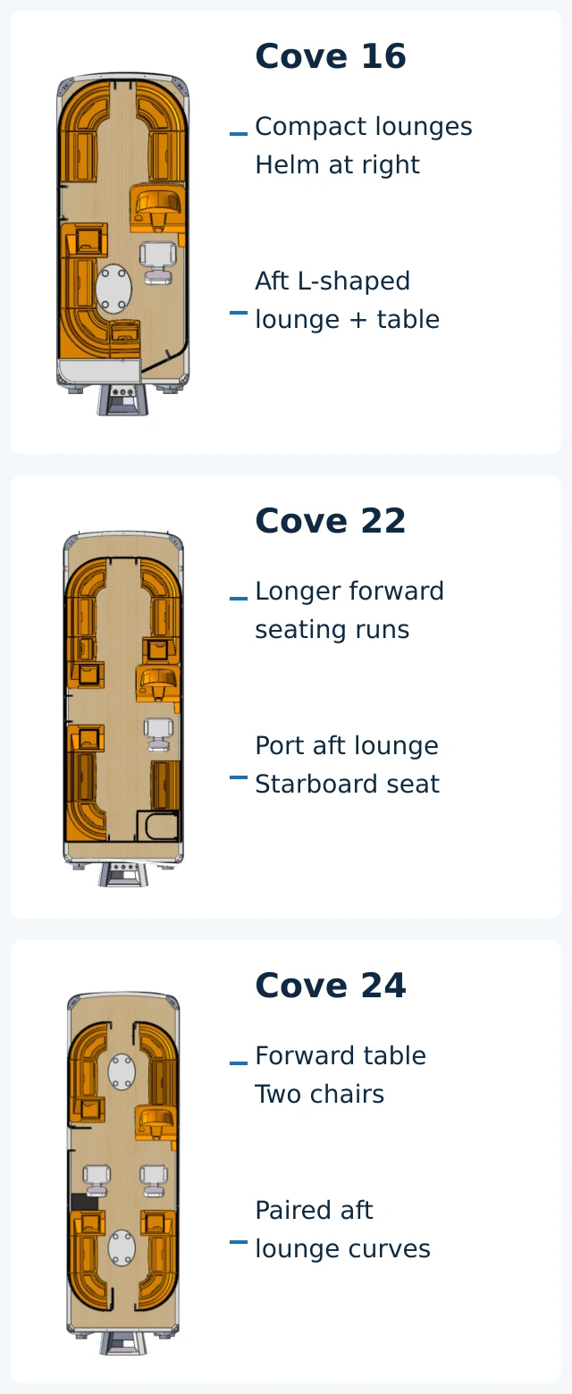
Shortlist Cove 16 if the compact arrangement covers your essentials. Compare Cove 22 and Cove 24 when a particular seating zone or movement conflict remains unresolved. Seat cushions, chairs and floor area do not establish the boat’s permitted passenger or load rating.
What does 2.3 m vs. 2.6 m beam change?
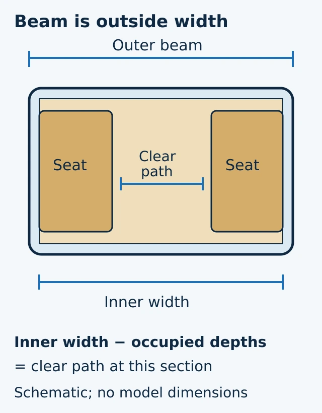
The outside width difference is 0.30 m: 2.6 − 2.3 = 0.30 m, or 300 mm. How much reaches the central aisle depends on the inner fence position, furniture depth, helm footprint and selected layout. Ask the supplier to mark the usable inner width and the narrowest passage at the same cross-sections on both beam drawings. Do not assign all 300 mm to walking space.
For a simple cross-section, clear path width = usable inner width − port occupied depth − starboard occupied depth. Hypothetical inputs: 2.10 m − 0.65 m − 0.70 m = 0.75 m. These assumed dimensions explain the width budget; they are not Cove measurements or a recommended access clearance. Recheck wherever the helm, a seat, table or fitting changes the occupied depth.
Use occupied positions as well as the empty plan: ask where a chair moves, where feet rest and where a stowed item projects. If you have a mobility or boarding requirement, provide its actual dimensions and discuss the complete route, turning space and gate opening. Beam alone cannot establish accessibility compliance.
| Beam choice | Reason to inspect | What could rule it out |
|---|---|---|
| 2.3 m | A narrower outside footprint is a priority | The configured route, gate or furniture arrangement does not meet your measured needs |
| 2.6 m | The wider drawing resolves a specific seating or passage conflict | The actual package conflicts with berth, storage or route restrictions |
Fit screen: if confirmed maximum package width is equal to or greater than a clear opening, that opening provides no positive width allowance. Stop that fit assumption and request another arrangement or access route. A positive difference still needs handling and movement allowances agreed with the marina or transport provider; it is not proof of fit.
Match the boarding gate to your dock
Choose a gate by the side and position from which you actually board. On the reference plans, the port-side opening and bow route help orient the discussion, but a drawn opening does not establish hinge side, swing direction or clear opening width. Mark the dock alongside the proposed plan and ask the seller to label each intended boarding point.
| Check | Record on the selected drawing | Problem this prevents |
|---|---|---|
| Dock approach | Bow, port or starboard; dock height and boarding location | Buying a layout whose usable gate faces away from the normal approach |
| Gate operation | Hinge side, swing direction, fully open position and clear opening | A seat, table or dock fitting blocks the gate’s movement |
| Route inside | Narrowest width from gate to seating and helm, with chairs/table in use | An open gate leads directly into a furniture bottleneck |
| Stowage | Cooler, bags and other carried equipment in their intended locations | The only clear route becomes the storage area |
| Berth fit | Configured outer dimensions and marina-confirmed usable limits | Boat beam is mistaken for the full occupied berth width |
Keep boarding and passenger-limit questions separate. Ask for the actual boat’s loading instructions and ratings; a convenient gate or extra lounge does not increase permitted capacity.
Check road width for the complete transport package
A 2.3 m or 2.6 m boat beam does not settle road transport legality. Obtain the maximum loaded width, height, length and weight for the actual boat, trailer, engine and fitted equipment, then ask the transport provider and relevant road authorities to check the full route. State or local roads and the destination may impose different requirements.
For US context, FHWA’s 23 CFR 658.15 width FAQ describes 102 inches or its approximate 2.6 m metric equivalent for commercial motor vehicles on the National Network, with a Hawaii exception. The same FAQ explicitly says that federal rule does not apply to noncommercial vehicles such as recreational vehicles. That federal figure is therefore not blanket permission to tow a recreational boat of a stated beam. Have the authority or hauler identify the applicable vehicle classification, loaded-width measurement, route rules and any permit conditions.
Keep the hauler’s route confirmation with the selected-beam drawing and written package dimensions. If transport scope or permission remains pending, keep that cost and arrangement pending in the offer too.
Compare costs over the same ownership period
Compare complete configurations over the same years and expected use. The pontoon boat cost guide separates purchase scope from recurring costs. For this size decision, obtain local figures for the selected boat’s storage or berth and transport arrangements before deciding that a shorter or narrower package costs less overall.
| Cost line | Basis to keep consistent | Hidden omission to resolve |
|---|---|---|
| Delivered acquisition | Same engine/equipment scope, destination and currency | Trailer, permits, onward delivery, unloading or setup excluded |
| Storage or mooring | Same number of months and confirmed package dimensions | A quoted space cannot accept the selected width or length |
| Recurring ownership | Same years and use; local insurance and service estimates | Unknown amounts entered as zero, or included service counted twice |
| Changes to make the layout usable | Written parts/labor scope for any agreed change | Repeat transport, installation or a replacement fitting outside the offer |
Same-period ownership cost = delivered acquisition + storage/mooring + insurance + fuel/service + other applicable charges during that period. Use actual local quotations for each line. As a workload example only, two planned transport movements per year over three years give 2 × 3 = 6 movements to price on the same basis for each option; this assumes no trip cost or savings.
What to send us
Send your preferred Cove size, beam choice and layout questions on WhatsApp to discuss configuration and regional supply. If you are still deciding the boat family, return to the buying guides. Include the dimensions that could reject a choice, so the conversation focuses on a layout you can use and a package you can receive.
| Item | Why we need it | Example format |
|---|---|---|
| Model and beam | Identifies the drawing to discuss | Cove 22, compare 2.3 m and 2.6 m, or undecided |
| Seating and gear | Locates the space conflict | Marked plan with cooler, bags, table and chairs |
| Boarding | Frames gate and route questions | Dock on port side; photo and measured access needs |
| Limiting dimensions | Screens berth, storage and transport fit | Clear opening, usable berth, known route restrictions; units included |
| Destination and package | Frames supply and delivered-cost scope | Country/region; engine/trailer requested; unresolved items listed |
Check the message draft and send it in WhatsApp. Opening the chat does not send your request, reserve a boat or confirm the final configuration.
Method and sources
Updated October 2026; sources checked October 20, 2026. The model table uses SEAVIA’s published Cove reference specifications. The plan comparison describes authorized reference drawings, with each resized independently for legibility. Those drawings do not provide the selected-beam dimensions needed to approve aisle width, gate movement or dock fit.
The beam subtraction uses published reference values. The clear-path and transport-workload examples use explicitly assumed inputs. FHWA provides the federal commercial-vehicle scope described above; route-specific recreational towing requirements remain a matter for the applicable authorities and transport provider. Final dimensions, layout, equipment and destination arrangements belong in the written configuration and offer.