
Engine fitment measurements
How to measure outboard shaft length: transom and motor pod checklist
Updated
A shaft mismatch can mean re-rigging an engine package. To measure outboard shaft length, identify the bracket’s transom seating reference and measure down to the anti-ventilation plate, then compare it with the boat’s mounting-height record. This checklist separates a conventional transom, a pontoon motor pod and a bow-mounted trolling motor’s waterline measurement.
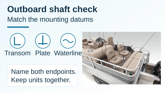
Start with three separate measurements
A deck-to-waterline measurement cannot select an outboard shaft. Record the engine’s bracket-to-plate dimension and the boat’s mounting-face-to-bottom reference as separate inputs, then check the exact engine manual and boat drawing together. For a bow-mounted trolling motor, start a different record from its mounting surface to the waterline. Use the SEAVIA configurator to record preferences; a selected option still needs a configuration-specific fitment decision.
| Input or item | Value or source to record | Why it matters |
|---|---|---|
| Outboard identity | Full model code, year/serial reference and manual | Identifies the shaft variant and its installation guidance |
| Outboard dimension | Bracket seating reference to anti-ventilation plate, with units | Avoids measuring overall engine height or the propeller shaft |
| Boat mounting height | Mounting face/top datum to designated hull or pod bottom reference | Makes the boat and engine records comparable |
| Trolling motor input | Mounting surface to waterline at the intended location; load noted | Uses waterline rather than the outboard’s hull-bottom reference |
| Installation context | Bracket/setback, existing mount and intended water conditions | Flags details a nominal shaft label cannot resolve |
Where do you measure the outboard and transom?
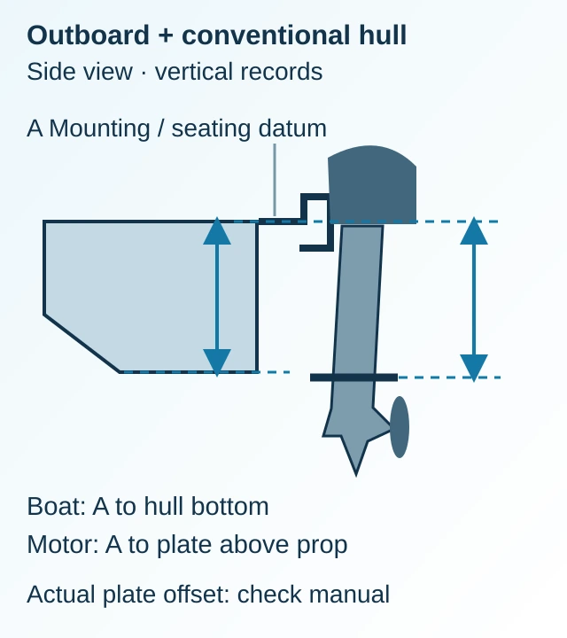
For a conventional transom-mounted outboard, identify the surface where the engine bracket seats on the transom and the anti-ventilation plate above the propeller. Record the vertical bracket-to-plate distance with the engine upright. On the boat, record the corresponding mounting-top datum to the hull-bottom reference at the engine centerline. Label both endpoints on a photo; a tape laid along a sloping transom can describe a different distance.
The anti-ventilation plate is the broad plate above the propeller, sometimes called the cavitation plate. The skeg below the gearcase and the propeller center are different endpoints. Copy the manufacturer’s dimension name and drawing reference alongside your measurement, especially when assessing an existing engine whose nominal shaft class is uncertain.
Yamaha’s portable-outboard guidance checks height with the engine vertical and a straightedge extended along the keel toward the plate. It describes the plate even with, or slightly below, the hull bottom for that application. Use this as a way to understand the reference points; the selected engine and hull instructions determine the actual mounting position. Incorrect height or disturbed inflow can affect cooling, while excessive immersion adds resistance.
How should you compare 20-inch and 25-inch shafts?
Use 20-inch and 25-inch labels to identify candidate variants, then confirm the actual engine dimensions and approved boat installation. Current OEM specifications include 20 in / 508 mm and 25 in / 635 mm transom-height classes. Those labels do not establish the exact bracket-to-plate tape measurement of every engine, or prove that a pontoon takes one class rather than the other.
Nominal class difference = proposed class − requested class. Worked example with assumed inputs: 25 in − 20 in = 5 in; 5 × 25.4 = 127 mm. This flags a class discrepancy to resolve before ordering. It does not tell you to move the engine 5 inches, choose a mounting hole or add a jack plate.
If the measured geometry falls outside the selected engine’s documented mounting range, hold the fitment decision and request a matching drawing or revised package. Do not round an awkward measurement into a convenient class. Pontoon boat motor size also involves permitted horsepower and installed weight; shaft length cannot establish either. Check the boat’s rating and builder-approved engine package separately.
| Record | What it establishes | Dominant Failure Mode & Prevention |
|---|---|---|
| 20 in nominal class | A candidate variant corresponding to a nominal 508 mm transom-height class | A label hides the actual datum: compare the engine drawing with the boat’s named reference |
| 25 in nominal class | A candidate variant corresponding to a nominal 635 mm transom-height class | A longer variant is assumed compatible: obtain a written match for the mount and hull |
| Installed plate position | The plate’s actual relationship to the designated bottom reference | Too high can disrupt propeller immersion/cooling; too low adds drag: installer checks the exact manual and water flow |
What changes when a pontoon has a motor pod?
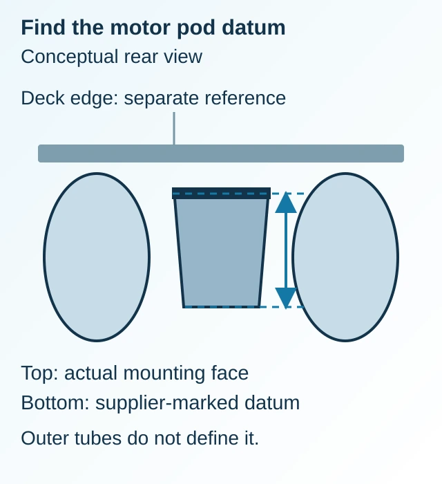
Measure at the actual engine mounting face on the motor pod, and ask the boat supplier to identify the bottom reference used for engine-height selection. A pontoon’s deck edge, outer tube and pod can sit at different heights. For the pontoon range, request the drawing for the selected model and configuration rather than transferring a measurement from another boat’s deck.
- Mark the top/seating datum of the engine mounting face on the pod drawing or a labelled side photo.
- Ask the supplier to mark its designated pod/hull-bottom or keel-line reference, then record the vertical separation in inches or millimeters.
- Record the engine’s fore-and-aft position or setback separately. A setback dimension cannot substitute for vertical mounting height.
- Keep the loaded waterline as another record. Request confirmation of the proposed shaft variant, installed plate position and cooling-water access for that exact assembly.
How do you check a trolling motor’s shaft length?
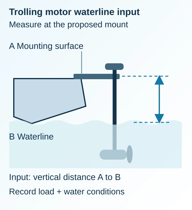
Measure vertically from the intended trolling motor mounting surface to the waterline and record the boat’s load and measurement location. A bow mount and a transom mount use different selection charts. For an aluminum fishing boat, check the actual bow mounting position, deployed reach and stowed space together; boat length alone cannot select a shaft.
The current Minn Kota bow-mount guide gives 42–45 in shafts for a 16–22 in bow-to-waterline input, and 48–52 in shafts for a 22–28 in input. Its rough-water instruction adds 5 in to the waterline measurement before selection. These are OEM guide ranges, with model/control-type exceptions; confirm the exact motor manual, especially at overlapping band endpoints.
Chart lookup input = measured mounting-surface-to-waterline distance + the allowance required by the applicable guide. Worked example with assumed inputs under that bow-mount guide: 20 in + 5 in rough-water allowance = 25 in; the 25 in lookup falls within the 22–28 in band, whose listed shaft range is 48–52 in. Confirm an available motor and its deployment/stow requirements before specifying it.
Rule of thumb for that guide: when the adjusted input is 25 in, use its 22–28 in row rather than the row for the unadjusted 20 in measurement. A short shaft can leave the propeller insufficiently submerged. Additional shaft length does not establish enough thrust to hold in current; thrust, electrical supply and mounting suitability need their own review.
Copy this measurement and fitment checklist
Copy the rows below into your notes and fill in the measurement, units and evidence reference. Write pending where the supplier must provide an answer. Label photos with the row name so the installer can distinguish a measured input from an approved specification. Return to the buying guides for the wider boat-selection decisions.
| Record to complete | Your value / status | Evidence to attach |
|---|---|---|
| Boat and engine identity | Boat/configuration: ___; engine variant: ___ | Model code, serial/year reference and matching manual |
| Boat mounting height | ___ in or mm; endpoints: ___ | Annotated transom/pod drawing with centerline and bottom datum |
| Engine bracket to plate | ___ in or mm; nominal class: ___ | Upright side photo and manufacturer’s dimension reference |
| Mount arrangement | Bracket/setback: ___; existing installation: ___ | Side and rear views; installed plate position if documented |
| Trolling input | Bow/transom: ___; waterline distance: ___; load: ___ | Mount location and waterline photo; exact motor/control type |
| Chart and conditions | Guide revision: ___; allowance: ___; lookup: ___ | Selected OEM row, intended water conditions and stow/deploy review |
| Fitment confirmation | Shaft/power/weight: ___; installer: ___; pending: ___ | Written configured package and named handover checks |
Compare installed scope before sending the record
Compare the same first-season period and currency across offers. First-season total = installed boat/engine package + excluded delivery/setup + planned maintenance and storage + any separately quoted correction work. Keep included installation costs out of the exclusions column to avoid counting them twice. The outboard hydraulic steering and helm rigging checklist helps separate the engine from steering, batteries and fuel-system scope.
Ask who pays for lifting and re-rigging if the supplied shaft variant differs from the agreed drawing, whether another launch or commissioning visit is included, and who resolves a failed fitment check. Use actual written amounts for each offer; a cheaper engine-only line can omit those jobs.
| Item | Why we need it | Example format |
|---|---|---|
| Boat/configuration and destination | Identifies the package and regional supply question | Page link or model name; country/region |
| Engine and transom/pod record | Identifies the shaft and datum question | Full engine code; named endpoints; in/mm; labelled photos |
| Trolling measurement and conditions | Identifies the chart and mounting question | Mount location; waterline distance/load; intended conditions |
| Unresolved installation scope | Shows what must be agreed in writing | Installer; included/excluded/pending jobs |
Send your measurement record on WhatsApp with the boat/configuration, engine identity, labelled transom or pod photos, trolling-mount waterline input and destination. Ask SEAVIA to discuss the proposed package and the items requiring supplier or installer confirmation. Opening the draft does not send it; send the message in WhatsApp to share your request.
Method and sources
Updated October 2026; sources checked October 20, 2026. This measurement checklist combines OEM reference-point guidance, nominal transom-height classes and a current bow-mount selection chart. Yamaha’s article concerns portable outboards; Honda’s specifications illustrate shaft classes; Minn Kota’s chart applies to its own motor-selection guidance. None assigns a shaft variant or horsepower rating to a SEAVIA model.
The drawings explain measurement relationships and contain no model dimensions or installation tolerances. The class-gap and rough-water calculations use stated hypothetical inputs. Keep the selected boat drawing, engine/motor manual and installer’s written configuration together for final fitment and handover.